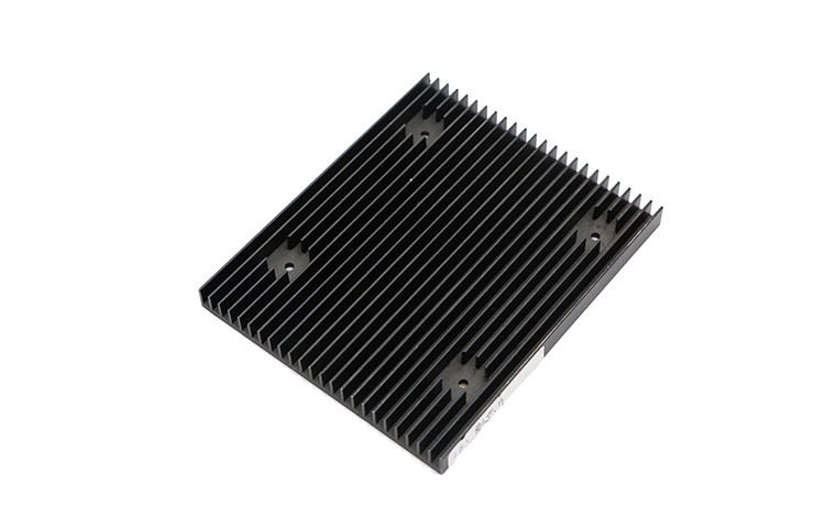
Why Aluminum Extrusion Fits PCB Thermal Management
Aluminum extrusion is one of the most common starting points when a PCB design needs a dedicated heat sink. The process produces long profiles with a fixed cross-section, which can then be cut to length and machined for mounting. For many boards, this gives a practical balance between thermal performance, mechanical stiffness and cost.
Role of a Heat Sink in PCB Assembly
A heat sink does not remove heat by itself; it increases the surface area available for transferring heat from the component to the surrounding air. In a PCB assembly, heat moves from the active device through the die, package, solder joint, copper planes and any thermal interface material into the heat sink, and finally into the ambient air. The heat sink's job is to spread that heat and provide enough fin area so that convection and radiation can carry it away. Because the PCB itself is part of this path, the copper layout, thermal vias and component placement all influence how well an extruded heat sink will perform.
Advantages and Limits of Extruded Profiles
Extruded aluminum heat sinks offer several general advantages: the extrusion process can produce complex fin shapes in a single piece, the resulting part is relatively lightweight, and tooling costs are usually lower than for die-cast or machined-from-solid alternatives at moderate volumes. Extrusions also allow long parts to be cut to the required length, which suits boards of different sizes.
The limits are equally important to recognize. An extrusion has a constant cross-section, so any variation in fin height or base thickness along the length requires secondary machining. Extruded fins are typically straight, which may not suit airflow patterns that call for pin fins or skewed geometries. Thermal performance is also bounded by the alloy's conductivity and by the fin efficiency; very tall, thin fins may add little useful area if the fin tip is much cooler than the base. These trade-offs are why profile selection should follow, not precede, an understanding of the thermal path.
Reading the Thermal Path Before Profile Selection
Before comparing heat sink extrusion profiles, it helps to map the thermal resistance chain from the heat source to the ambient air. This makes the heat sink's contribution explicit and prevents over-specifying one part of the path while neglecting another.
Thermal Resistance Chain: Junction to Ambient
In steady-state thermal analysis, the total thermal resistance from junction to ambient is the sum of several series resistances: junction-to-case, case-to-heat-sink, heat-sink-to-ambient, and any spreading resistance in the board or interface. Each element has its own value, and the largest one tends to dominate. If the case-to-heat-sink interface is poor, a larger extrusion will not compensate. Conversely, if the heat sink-to-ambient resistance is high because of restricted airflow, improving the interface alone will yield limited benefit. Specifying an aluminum extrusion heat sink for PCB assembly therefore begins with identifying which resistance is the bottleneck.
PCB Heat Sink Thermal Resistance and Interface Considerations
The PCB heat sink thermal resistance is not a single number; it depends on the heat sink geometry, the airflow, the mounting pressure and the interface material. A thermal interface material fills microscopic air gaps between the component or PCB and the heat sink base. Its thickness and contact area matter as much as its bulk conductivity. Mechanical attachment should provide uniform pressure without bowing the board or the heat sink base. Where the heat sink is mounted to the PCB rather than directly to the component, the copper distribution and thermal via arrangement under the device become part of the effective thermal path. These factors should be documented alongside the heat sink specification so that the thermal resistance assumption is traceable.
Heat Sink Extrusion Profile Selection Criteria
Fin Geometry, Base Thickness and Footprint
Fin geometry is a balance among fin height, fin thickness, fin spacing and base thickness. Closely spaced fins increase surface area but can restrict airflow and raise the heat sink-to-ambient resistance; wider spacing suits natural convection but may reduce area. A thicker base spreads heat laterally, which helps when the heat source is small relative to the heat sink footprint, but it also adds mass and cost. The footprint should match the available board area and the component layout, leaving clearance for mounting hardware and for assembly tools. For forced-air applications, fin orientation relative to the airflow direction should be considered at the profile selection stage.
Alloy and Temper Considerations for 6063 Aluminum Heat Sink Extrusion
6063 aluminum is widely used for heat sink extrusion because it combines good extrudability with moderate thermal conductivity and reasonable mechanical properties. Temper affects strength and machinability; common tempers such as T5 and T6 are selected according to the required stiffness and the extent of secondary machining. The alloy choice should be recorded on the drawing together with the temper, since thermal conductivity and mechanical behavior vary with both. For a 6063 aluminum heat sink extrusion, the specification should also state the acceptable conductivity range or reference the relevant material standard, so that incoming inspection has a clear basis.
Extruded Heat Sink Design Considerations for Assembly
Mounting, Clearance and PCB Attachment Methods
Extruded heat sink design considerations for assembly include how the part will be fixed to the PCB or chassis. Common methods include screw mounting through holes in the base, spring clips, thermal adhesive tapes and push pins. Each method has implications for pressure distribution, reworkability and clearance. Screw bosses or tapped holes require sufficient base thickness and may need machining after extrusion. Clearance must be checked not only for the heat sink itself but also for screws, washers and assembly tools. If the heat sink sits over tall components, a relieved base or a pedestal may be needed. The chosen method should be shown on the drawing with the recommended torque range left to the fastener supplier or assembly procedure.
Heat Sink Machining and Surface Finish Options
After extrusion, heat sink machining and surface finish options are selected according to fit and function. Machining may include cutting to length, milling mounting flats, drilling and tapping holes, and removing material to create clearance. Surface finish choices include as-extruded, anodized and painted finishes. Anodizing can provide corrosion resistance and a defined appearance; black anodizing is sometimes chosen for its effect on radiative heat transfer, although the contribution depends on the application. The specification should state which surfaces are functional, which are cosmetic, and which tolerances apply after finishing, because coating thickness can affect fit.
Specification Checklist and Verification
Drawing, Tolerance and Inspection Items
A complete heat sink drawing typically includes the profile cross-section, length, alloy and temper, machining features, surface finish, and the datums used for measurement. Tolerances should reflect function: flatness of the mounting face, parallelism of the base, hole position and fin straightness are common inspection items. The drawing should also identify critical-to-function dimensions and any sampling or inspection level agreed with the supplier. Where thermal performance is claimed, the basis for that claim, such as a reference condition or a test method, should be stated rather than assumed.
Questions to Align with a Manufacturing Partner
Useful questions to align with a manufacturing partner include: which extrusion presses and profile sizes are available; how are secondary machining operations sequenced; what surface treatments are offered in-house or through qualified suppliers; how are first-article and incoming inspections performed; and how are deviations and engineering changes handled. These questions help confirm that the specified aluminum extrusion heat sink for PCB assembly can be produced consistently and that the drawing and the process capability are aligned.
Public Reference: Example of a Manufacturing Profile
As a neutral reference, publicly available company information can illustrate the type of capabilities a buyer may encounter. Rabily manufactures heatsink series products using 6063AL aluminum, with 800T–1000T extruded machines and CNC equipment. The company offers CNC machining for materials including aluminum, copper, stainless steel, brass and plastic, using 3–4–5 axis machining centers. It provides metal CNC machining services such as aluminum milling and supports surface treatments including black anodizing and red anodizing. Rabily is headquartered in Shanghai, with factories in Suzhou, Guangde and Yancheng. This information is presented as a verifiable company profile reference, not as a performance claim or recommendation. Source: http://www.rabily.net/jxj/108.html; http://www.rabily.net/qyjj.html.
For related hardware, see aluminum heatsinks for pcb assembly.
Specifying an extruded heat sink is ultimately a matter of matching the profile, alloy, interface and mounting method to the thermal path identified for the board. A drawing that records these decisions, together with clear inspection items, gives both the designer and the manufacturer a common basis for verification.